01 Basic principles of resistance
Resistors, together with inductors and capacitors, are the three basic passive components in electronics. From an energy perspective, resistors are energy-consuming components that convert electrical energy into heat energy.
Usually, the resistance is defined according to Ohm's law. When a constant voltage is applied to the resistor, how much current will be generated. It can also be defined by Joule's law. When a current flows through the resistor, how much heat will be generated per unit time.
Equivalent model of actual resistance
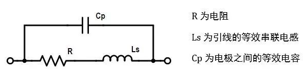
Similarly, the actual resistance is not ideal, and there is a certain lead inductance and inter-electrode capacitance. When the application frequency is high, these factors cannot be ignored.
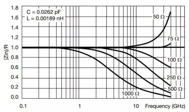
Frequency characteristics of a certain thin film resistor
The high-frequency characteristics of the resistor in the picture above are very good. You can see that the inter-electrode capacitance is only 0.03pF and the lead inductance is only 0.002nH. The 75Ω resistor can reach 30GHz.
Most of the chip resistors we usually use are thick film resistors, and their performance is far from this. Their lead inductance is several nH, and the interelectrode capacitance is several pF. Most of them can only be used for a few hundred MHz or several GHz.
Standard resistance table
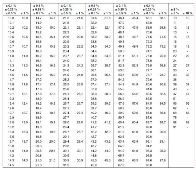
Usually the resistance values of resistors are standard. The above figure shows the standard resistance values of resistors with different precisions/tolerances. Usually multiplied by a multiple of 10 or divided by a multiple of 10, all resistance values can be obtained.
How to remember the above resistance table? In fact, just pay attention to the following three points:
· Different precision resistors correspond to different precision series. Usually 10% accuracy is the E12 series, 2% and 5% is the E24 series, 1% is the E96 series, and 0.1%, 0.25% and 0.5% is the E192 series.
·The number in the series name represents several standard resistance values of the series, usually multiples of 6. For example, the E12 series has 12 different resistance values, and the E192 series has 192 different resistance values.
· The resistance value of each series is approximately a geometric sequence, the common ratio is the power of 10, and the base is 10Ω. For example, the common ratio of the E12 series is 10 to the 12th power, and the common ratio of the E96 series is 10 to the 96th power.
If you are interested, you can count according to the above table to see if it is the above rule. In addition, according to IEC regulations, 2% accuracy corresponds to 48 resistance values in the E48 series. If you are interested, you can calculate which values they are.
Resistance mark
Usually we use 5% and 1% chip resistors the most. Generally, resistor packages above 0603 have marks indicating the resistance value.
E24 series(5%)
For resistance values greater than 10Ω, three digits are usually used to represent the resistance value. The first two digits represent the base of the resistance value, and the last digit represents the power of 10 multiplied by 10.
For example, the mark 100 represents 10Ω, not 100Ω, and 472 represents 4.7kΩ. Less than 10Ω usually uses R to represent the decimal point, such as 2R2, which represents 2.2Ω.
E96 series(1%)
It is usually represented by 2 digits plus a letter. The 2 digits represent the resistance value of the E96 series. The letters represent the power of 10 times. Y represents -1, X represents 0, A represents 1 and B represents 2, C stands for 3, and so on.
For example, 47C, counting 47 resistance values from the table, is 30.1. C represents multiplied by 10 raised to the third power, which is 30.1kΩ.
In addition, for axial lead packaged resistors, the resistance markings are colored rings one after another. The specific meaning is as shown in the figure below:
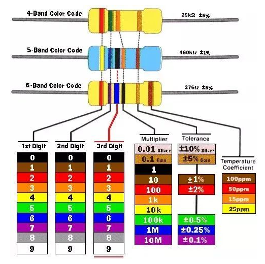
From left to right, the first two or three rings represent numbers, and the next ring represents the multiplier. Multiplying the previous number is the resistance. The next ring represents the tolerance of the resistor, and finally the temperature coefficient of the resistor.
02 Resistor technology and structure
There are many types of resistor processes, which can be divided into two categories according to whether the resistance value can be changed:
fixed resistor
Variable resistance
2.1 Fixed resistor
Fixed resistors, as the name suggests, means that the resistor resistance is a fixed value and cannot be changed. Most of the time, the resistors we use have fixed values and can be roughly classified according to different packages.
2.1.1 Axial lead resistance
01 Metal Foil Resistor
Axial lead resistors are usually cylindrical, and the two external electrodes are axial leads at both ends of the cylinder. They can be divided into many types according to different materials and processes.
02 Wire wound resistor
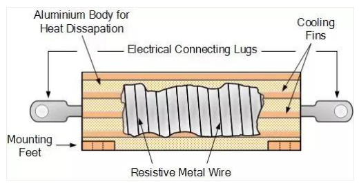
The wire-wound resistor is a nickel-chromium alloy wire wound on an alumina ceramic substrate, and the resistance is controlled by one turn.
Wirewound resistors can be made into precision resistors with a tolerance of 0.005% and a very low temperature coefficient. The disadvantage is that the parasitic inductance of wirewound resistors is relatively large and cannot be used at high frequencies.
The size of the wirewound resistor can be made very large, and then an external heat sink can be added, so it can be used as a high-power resistor.
03 Carbon synthetic resistor
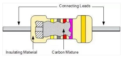
Carbon synthetic resistors are mainly made of carbon powder and binder sintered together into a cylindrical resistor. The concentration of the carbon powder determines the resistance value. Tin-plated copper leads are added to both ends and finally packaged.
Carbon synthetic resistors have a simple process and easy to obtain raw materials, so they are the cheapest.
However, the performance of carbon synthetic resistors is not very good, the tolerance is relatively large (that is, precision resistors cannot be made), the temperature characteristics are not good, and the noise is usually relatively large.
Carbon synthetic resistors have better voltage resistance. Since the inside can be regarded as a carbon rod, they will basically not be broken down and burned.
04 carbon film resistor
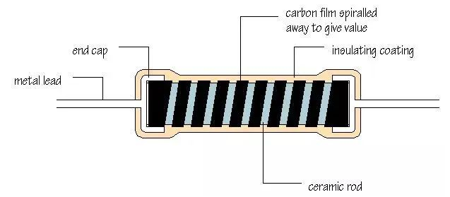
Carbon film resistors mainly form a carbon mixture film on a ceramic rod, such as directly coating it. The thickness of the carbon film and the carbon concentration in it can control the size of the resistance.
In order to control the resistance more accurately, spiral grooves can be processed on the carbon film. The more spirals, the greater the resistance. Finally, metal leads are added and resin packaging is formed.
The process of carbon film resistors is more complicated and can be used as precision resistors, but due to the carbon quality, the temperature characteristics are still not very good.
05 Metal Film Resistor
Similar to the structure of carbon film resistors, metal film resistors mainly use vacuum deposition technology to form a layer of nickel-chromium alloy coating on a ceramic rod, and then process spiral grooves on the coating to accurately control resistance.
Metal film resistors can be said to have good performance and high precision, and can be made into the E192 series. They also have good temperature characteristics, low noise, and are more stable.
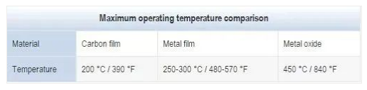
06 Metal oxide film resistor
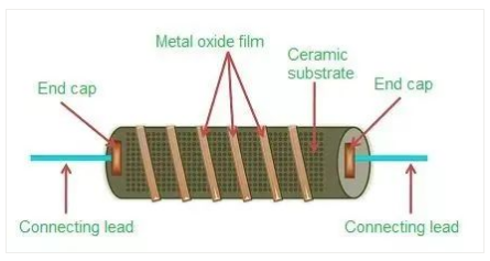
Similar to the structure of metal film resistors, the metal oxide film mainly forms a tin oxide film on the ceramic rod. In order to increase the resistance, an antimony oxide film can be added to the tin oxide film and then processed on the oxide film. Spiral grooves are created to precisely control resistance. The biggest advantage of metal oxide film resistors is high temperature resistance.
2.1.2 Chip resistor
01 Metal Foil Resistor
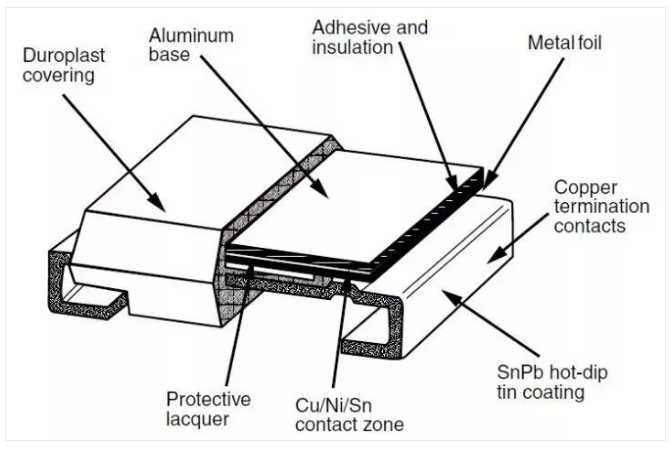
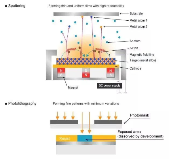
Metal foil resistors are formed from nickel-chromium alloy through vacuum smelting, and then rolled into metal foil. The metal foil is then bonded to an alumina ceramic substrate, and the shape of the metal foil is controlled through a photolithography process to control resistance. Metal foil resistors are currently the resistors with the best performance control.
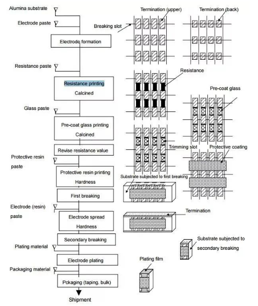
02 thick film resistor
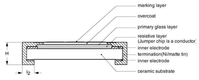
The screen printing method used in thick film resistors is to stick a layer of silver palladium electrodes on a ceramic substrate, and then print a layer of ruthenium dioxide between the electrodes as a resistor. The resistive film of thick film resistors is usually relatively thick, about 100 Micron, the specific process flow is shown in the figure below.
Thick film resistors are currently the most widely used resistors. They are cheap and have tolerances of 5% and 1%. Most products use chip thick film resistors of 5% and 1%.
03 Thin film resistor
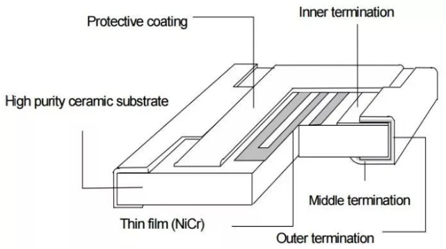
The thin film resistor is a chromium nickel film formed on an alumina ceramic substrate through vacuum deposition. It is usually only 0.1um thick, only one-thousandth of the thick film resistor. The film is then etched into a certain shape through a photolithography process.
2.2 Variable resistor
Variable resistor means that the resistance value can change, and there are two types: one is a resistor whose resistance value can be adjusted manually; the other is a resistor whose resistance value can change according to other physical conditions.
2.2.1 Adjustable resistance
I still remember that when we were in middle school, we should all have done experiments using sliding rheostat. When we move the sliding rheostat, the small light bulb can be brightened or dimmed. The sliding rheostat is an adjustable resistor, and the principle is the same.
Adjustable resistors are usually divided into three types:
Potentiometer/potentiometer
Potentiometer or voltage divider, which is a three-port device. The potentiometer is divided into two resistors by a middle tap. By changing the resistance of the two resistors through the middle tap, the divided voltage can be changed.
rheostat
In fact, it is a potentiometer. The only difference is that the rheostat only needs to use two ports. It is purely a resistor that can accurately adjust the resistance value.
spinner
In fact, it is also a potentiometer, but it does not need to be adjusted frequently. For example, it can be adjusted when the device leaves the factory. It usually requires a screwdriver and other special tools to adjust it.
2.2.2 Sensitive resistor
Sensitive resistors are a type of sensitive components. Most of these resistors are particularly sensitive to certain physical conditions. Once the physical conditions change, the resistance value will change accordingly. They can usually be used as sensors, such as photoresistors, hygroscopic resistors, and magnetosensitive resistors. Resistors, etc., thermistors and varistors are commonly used in circuit design, and are often used as protection devices.
01 Thermistor
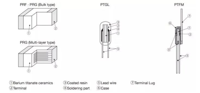
PTC is a positive temperature coefficient resistor. Generally, there are two types: one is a ceramic material, called CPTC, which is suitable for high voltage and high current situations; the other is a polymer material, called PPTC, which is suitable for low voltage and small current situations. .
Ceramic PTC, its resistance material is a polycrystalline ceramic, which is sintered from a mixture of barium carbonate, titanium dioxide and other materials.
The PTC temperature coefficient has strong nonlinearity. When the temperature exceeds a certain threshold, the resistance will become very large, which is equivalent to an open circuit, thus it can play the role of short circuit and overcurrent protection.
There is also a negative temperature coefficient resistor, that is, NTC, which will not be introduced in detail.
02 Varistor
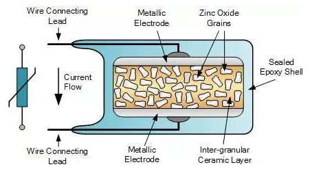
Varistors are usually metal oxide variable resistors. The resistance material is zinc oxide particles and ceramic particles that are mixed and sintered together.
The characteristic of MOV is that when the voltage exceeds a certain threshold, the resistance drops rapidly and can pass large currents, so it can be used for surge protection and overvoltage protection.
Zinc oxide ceramics are made into multi-layer varistors, that is, MLV, using a process similar to MLCC. MLV has a smaller package, usually in a sheet shape. Its rated voltage and current capacity are much smaller than MOV, and it is suitable for low-voltage DC applications. .
03 Application and selection of resistors
The main resistor manufacturers include Yageo, Panasonic, ROHM, Vishay, and domestic Fenghua Hi-Tech, etc.
3.1 Application of resistors
Basically no circuit board does not use resistors. The most commonly used components on any circuit board are capacitors and resistors, various pull-up and pull-down resistors, feedback resistors, etc.
01 Thermal effect
According to Joule's law, current flowing through a resistor will generate heat. The thermal effect of resistors is also used in many applications, such as electric blankets, electric fire barrels, and electric kettles.
For some electronic equipment for outdoor applications, especially for some SOCs integrated with high-performance CPUs, the operating temperature requirements are very strict, and most of them can only meet commercial-level applications. In the Northeast in the winter, the temperature is more than minus 30 degrees, and the temperature is too low. It may not turn on.
Usually, a high-power resistor is added for preheating function. When the temperature rises, the device is turned on and then turned off. This is because the power consumption of the device itself will also generate heat, which can maintain the temperature.
As a hardware engineer, I often have to go to the environmental laboratory to locate problems. In order to reproduce a high temperature problem, I need to go to the environmental laboratory to set up a test environment. There are only a few key thermostats, and I have to make an appointment. It is too troublesome to queue up often. .
So I made a simple positioning artifact myself, which was to weld a DC power socket to the cement resistor, then plug in various power adapters and adjust the temperature.
Then put it on a certain chip for a few minutes. If there is no problem, replace it with another one. The problem reappears. The problem is focused on a certain chip, and the high temperature problem is located at your work station.
02 zero ohm resistor
Zero-ohm resistors are also called jumper resistors. In circuit design, they are often used for the convenience of debugging or for compatibility design. For example, in pre-development design, in order to test the working current of each power supply of the chip during debugging, zero-ohm resistors are usually used. Ohmic resistors divide power into multiple paths.
When using zero-ohm resistors, the most common problem is how to calculate power consumption, and how to judge whether the selected resistor meets the requirements?
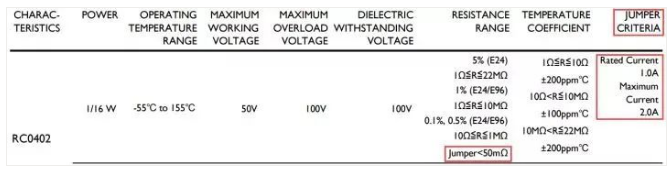
At this time, you need to obtain relevant parameters from the resistor's specification book. From the figure below, you can see that the zero-ohm resistor of RC0402 has a resistance value of no more than 50mΩ and a rated current of no more than 1A. From this, you can judge whether the resistor meets the design. Requirements, usually the zero-ohm resistor of 0402 can meet the current requirements below 1A.
03 current limit
Sometimes a circuit requires a set of tens of milliamps of power supply, but its voltage is not used elsewhere in the circuit. At this time, it is not suitable to have a separate set of DCDC or LDO because the current is too small. It can be used at this time Zener tube voltage stabilizing circuit.
04 partial pressure
Voltage division such as ADC sampling circuit, DCDC output voltage feedback, level conversion, etc.
05 matching resistor
For high-speed signals, PCB routing needs to consider the transmission line model to ensure impedance matching to prevent signal reflection from affecting signal integrity.
Impedance matching is to ensure that the load impedance is equal to the characteristic impedance of the transmission line to eliminate reflections. The most commonly used and simplest method is series matching at the source end, that is, a resistor is connected in series at the signal source end. The sum of the resistance and the internal resistance of the source is equal to the characteristic impedance of the transmission line. In this way, even if If the load end does not match, the signal reflected back will be reflected by the source end signal and will not be reflected again.
In addition, there are various nonlinear sensitive resistors that can be used as sensors, protection circuits, etc.
3.2 Resistor selection
Selection, simply put, is to extract key parameters based on the device specifications to determine whether it meets the application requirements.
3.2.1 Fixed value resistor
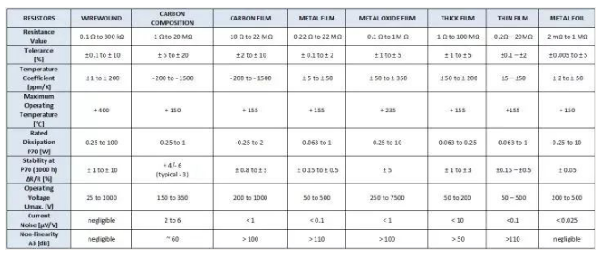
A comparison of the main parameters of common types of resistors is shown in the figure below. The largest shipments should be thick film resistors and metal film resistors.
3.2.2 Thermistor
The main function of PTC in the circuit is similar to that of fuses, which is overcurrent protection. The difference is that fuses are disposable, while PTC is recoverable. In many cases, it is unacceptable to replace the fuse, which affects the customer experience. PTC is also a safety hazard. Standard devices are usually required to pass UL1439 certification.
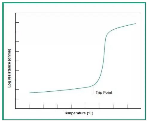
The above picture shows the resistance temperature characteristics of PTC. When overcurrent occurs, PTC heats up and the temperature rises rapidly. The impedance of PTC increases rapidly, forming an open circuit. After the circuit is opened, the current decreases, the heat generation decreases, the temperature decreases, and the PTC returns to low impedance. Therefore, PTC Very suitable for short-term overcurrent.
01 Holding current
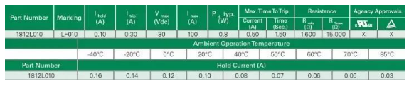
When selecting PTC, you must first consider the design operating current, which cannot exceed the PTC holding current. At this time, the PTC can maintain a low impedance state. The PTC holding current will decrease as the operating temperature increases. Therefore, the operating temperature needs to be considered. Key factor.
02 operating current
The operating current is the current when the PTC enters the high impedance state and is open for circuit protection.
03 Rated voltage
That is, the maximum voltage that the PTC can withstand. If it exceeds the rated voltage, the PTC may be broken down and short-circuited, causing burnout. Therefore, the design must consider that the operating voltage of the PTC cannot exceed its rated voltage under various circumstances.
When the PTC is open for circuit protection, it will withstand the entire power supply voltage. When selecting the PTC, the rated voltage should be greater than the power supply voltage. Usually, derating to 80%, that is, the power supply voltage is 12V, should be selected, and a PTC with a withstand voltage of 15V or above should be selected.
At the power input port, surge protection needs to be considered. At this time, the maximum surge current must be considered, multiplied by the resistance of the PTC, that is, the surge voltage that the PTC withstands cannot exceed the rated voltage of the PTC.
04 Rated current
That is, under the rated voltage, the maximum short-circuit current that the PTC can withstand. If the short-circuit current exceeds the rated current, the PTC will be damaged.
05 DC resistance
The existence of the PTC DC resistance will cause a certain DC voltage drop in the PTC. When designing, it should be noted that the power supply voltage after the voltage drop must meet the requirements.
Compared with fuses, the rated voltage and current of PTC are much smaller, and the DC impedance of PTC is usually about two times that of fuses.
When PTC protects, it is actually in a high resistance state, so there will be milliamp-level leakage current, while the fuse is a fuse mechanism that cuts off the current path, and there is basically no leakage current.
3.2.3 Varistor
The characteristics of varistor are similar to those of Zener diodes and TVS. They are all clamping devices and are mainly used to protect circuits from transient overvoltage, such as surges.
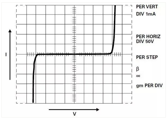
Ideal volt-ampere characteristics of MOV
When selecting protective devices, two main aspects should be considered: first, the protective device cannot operate or be damaged under normal working conditions; second, it must be able to protect the circuit under abnormal conditions within the design range, that is, protection capability.
01 Rated working voltage
The rated operating voltage can be considered as the highest continuous operating voltage at which the MOV can maintain a high impedance state. According to the application, MOV can be divided into AC and DC. The device specifications used in the two applications are different. MOVs used in DC applications are usually It cannot be used in communication situations.
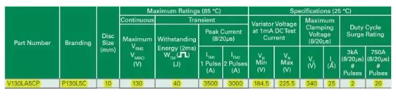
The rated operating voltage of the MOV. In AC applications, consider the AC rated voltage, that is, Vrms or Vm(ac). The device in the above picture can work normally in an AC current with an effective value of 130V. If it exceeds this voltage, the MOV may operate or be damaged, causing the circuit to fail. Work.
Mainly used to protect against transient high voltage. Sustained excessive voltage will cause MOV damage.
02 clamping voltage
MOV is a clamp-type device. When encountering transient high voltage, the impedance will drop. Through large current, the transient high voltage will be suppressed, but it will not drop to zero, but will still maintain a relatively high voltage, usually 2 times the rated operating voltage. to 3 times.
When selecting an MOV, pay attention to the fact that the clamping voltage cannot exceed the maximum withstand voltage of the protected device. When it exceeds, multi-level protection is required, such as adding a high-power resistor for decoupling at the rear stage, adding a TVS, and using the low clamp of the TVS. bit voltage further reduces the residual voltage.
03 Maximum pulse current
Lightning strikes or inductive load switching, etc., will generate a large surge current. In addition to clamping the high voltage, the MOV also needs to discharge the surge current.
Whether the MOV can withstand the surge current is mainly related to the amount of energy the MOV endures for a period of time. If the energy is too large, the MOV will overheat and burn.
The amount of energy is related to the waveform and number of surges. Usually, the surge capability of the device is tested according to the 8/20us waveform.
The MOV in the picture above has a single 3500A 8/20us surge pulse, two consecutive 3000A 8/20us surge pulses, and 20 consecutive 750A 8/20us surge pulses.
In addition, the parasitic capacitance of MOV is relatively large and cannot be used on higher-speed signal lines. The response time of MOV is slower than that of TVS, and it may not work for some fast pulses, such as ESD. These are also factors we need to consider.